To design asynchronous clocks, you must understand a phenomenon called Clock Domain Crossing (CDC). However, CDC is a field that many engineers find difficult to understand and do not want to understand. I think it is because they perceive that it is an additional annoying task that they have to do while wanting to quickly create the desired function.
If CDC cannot be solved, the chip cannot be commercialized. As mentioned before, the latest SOC chips must be designed with an Asynchronous structure, and if they do, CDC issues will inevitably arise.
So, to understand the inevitable relationship between Asynchronous design and CDC, let’s first look at what CDC is. CDC stands for Clock Domain Crossing. It literally means moving between domains that use different clocks, and the clock is the standard for processing data.
When the CPU sends data at 3GHz and the audio receives data at 48kHz, CDC occurs because the data must cross different clock domains. The CPU sends billions of data per second, but the audio can only process 48,000 per second. In this case, the data is transmitted inconsistently, causing the sound to break up due to jitter, or the metastability problem makes it unclear whether the data is 0 or 1, which ultimately leads to data loss.
So how can we solve this? We can add a synchronizer that synchronizes the clocks between the two blocks that operate on different clocks, and process the data by sampling. Adding a synchronizer is not difficult. However, you need to apply one synchronizer per bit so that the data is accurately sampled whether it is 0 or 1.
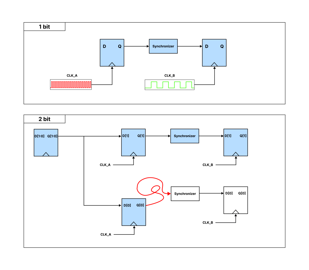
The structure where the synchronizer is inserted between the two blocks is expressed in the figure above.
In the upper figure where the data is 1 bit, one synchronizer is applied to 1 bit, and the data expressed in blue in the CLK_A domain is transferred to the CLK_B domain without any problems and becomes blue.
Then, what about the lower figure where the data is 2 bits?
It will work without a problem 99.9% of the time, but there is a 0.1% chance that it will malfunction.
This is because two bits must change at the same time, but two may not be sampled at exactly the same moment. If the two bits in the layout do not follow the same path and are physically placed far apart, the cycles that are placed far apart will operate slowly, and in the CLK_B domain, one data is transferred safely and becomes blue, but the other data is not transferred and does not become blue, i.e., a data mismatch occurs. And this can cause the entire system to malfunction.
In fact, this is a problem that is already known, so CDC tools these days inform you about the error and can be solved. However, the problem is that the system has become so complex that there are hundreds of errors of this kind, and engineers must be familiar with all of these errors and their solutions in order to develop commercially viable code.
In addition, when these IPs that have been developed with such difficulty are combined at the SOC system level, the clock relationship may be different from what was thought when each IP was developed, so clock system design becomes even more difficult.
Clock을 Asynchronous로 설계하려면 Clock Domain Crossing (CDC)이라고 불리는 현상을 이해해야 합니다. 하지만, CDC는 많은 엔지니어들이 이해하기 어려워하고, 또 이해하기 싫어하는 분야입니다. 원하는 기능을 빨리 만들고 싶은데, 추가적으로 귀찮게 해야 할 일이라는 인식이 좀 있어서 그런 것 같은데요.
CDC를 해결하지 못하면 칩을 상용화할 수 없습니다. 전에 언급한 것처럼 최신 SOC 칩은 무조건 Asynchronous구조로 설계해야 하고, 그렇게 되면 CDC 이슈는 필연적으로 발생할 수 밖에 없기 때문입니다.
그럼 Asynchronous design과 CDC의 필연적 관계를 이해하기 위해 CDC가 무엇 인지부터 먼저 살펴보겠습니다. CDC는 Clock Domain Crossing 문자 그대로 서로 다른 clock을 사용하는 domain 사이를 이동한다는 뜻이고, clock은 데이터를 처리하는 기준입니다.
CPU는 3GHz 기준으로 데이터를 보냈는데 오디오는 48kHz 기준으로 데이터를 받게 될 때, 데이터가 서로 다른 Clock Domain을 Crossing 해야 하기 때문에, CDC가 발생합니다. CPU는 초당 수십억개의 데이터를 보내는데, 오디오는 초당 48,000개만 처리할 수 있는 상황입니다. 이 경우, 데이터가 들쭉날쭉하게 전달되어 jitter로 인해 소리가 깨지거나, 메타안정성 (Metastability) 문제로 데이터가 0인지 1인지 알 수 없는 애매한 상태가 되어 결국 Data 손실이 일어나게 됩니다.
그럼 어떻게 해결하면 될까요?
서로 다른 clock으로 동작하는 두 블럭 사이에 clock을 맞춰주는 synchronizer를 넣어주고, 샘플링해서 데이터를 처리하면 됩니다. synchronizer를 넣는 것은 어렵지가 않습니다. 다만, 데이터가 0이든 1이든 정확하게 샘플링되도록 1bit 당 하나의 synchronizer를 적용해야 합니다.
위 그림으로 두 블럭 사이에 synchronizer를 넣은 구조를 표현해봤습니다.
데이터가 1bit인 위쪽 그림에서는 1bit에 하나의 synchronizer를 적용했고, CLK_A 도메인의 파랑색으로 표현된데이터가 CLK_B 도메인으로 문제 없이 넘어가 파랑색으로 되었습니다.
그럼 데이터가 2bit인 아래쪽 그림은 어떨까요?
99.9% 문제 없이 동작하겠지만, 0.1%는 오동작 할 가능성이 있습니다.
이유는 2개의 bit가 동시에 변해야 하는데, 정확히 같은 순간에 2개가 샘플링 되지 않을 수 있기 때문입니다. 레이아웃에서 2 bit가 동일한 경로를 따라가지 않고 물리적으로 멀리 배치되면, 멀리 배치된 사이클이 느리게 동작하게 되어 CLK_B 도메인에서 하나는 데이터가 무사히 넘어와 파랑색이 되었는데, 다른 하나는 데이터가 넘어오지 못해 파랑색이 되지 못한 상태, 즉 데이터 불일치가 발생합니다. 그리고 이것 때문에 전체 시스템은 오동작 하게 될 수도 있게 됩니다.
사실 이 부분은 이미 알고 있는 문제이기 때문에 요즘 CDC 툴들이 오류에 관해서 알려주고 있고, 해결도 가능합니다. 다만, 문제는 시스템이 너무 복잡해져서 이런 종류의 오류가 수백개가 넘어가고 있고, 이 모든 오류들과 해결 방법을 엔지니어가 숙지하고 있어야 상용화 가능한 코드를 개발할 수 있다는 점입니다.
게다가 이렇게 어렵게 개발된 IP들을 SOC 시스템 레벨에서 엮을 때는,
clock의 관계가 각각의 IP일때 생각했던 것과 달라질 수 있기 때문에, Clock 시스템 설계는 더욱 어려워지게 됩니다.